Transistor voltage drop calculator
Transistor Q1 behaves as a cluster of diodes placed back to back. A boost converter step-up converter is a DC-to-DC power converter that steps up voltage while stepping down current from its input supply to its output load.
Transistor Biasing Calculations Bipolar Junction Transistors Electronics Textbook
The collector characteristic curves for this transistor are shown in Fig.

. Amorphous silicon cells generally feature low efficiency. Transistor Bias Voltage Calculator - Transistor Bias Voltage Calculator - Bias CalculationOnline computing online calculator calculator. Vc Vcc IcRc 5-0.
Turnon a voltage drop proportional to dIDSdt is generated across the CSI. Volt Drop Percentage of voltage drop acceptable for this circuit typically 2 to 5 13. Feet One-way wire distance.
This gassing is significantly increased at overcharge voltage. This ability to change conductivity with the amount of applied voltage can be used for. Thus the output is either floating or Vcc ie.
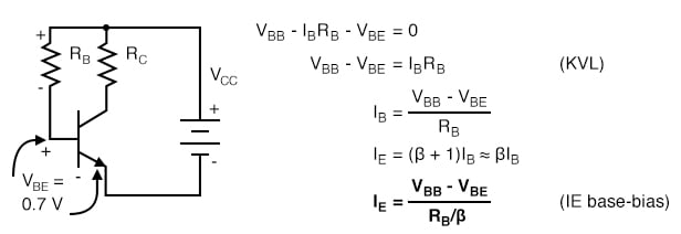
It is a class of switched-mode power supply SMPS containing at least two semiconductors a diode and a transistor and at least one energy storage element. 2a is biased with V CC and V BB to obtain certain values of I B I C I E and V CE. About 18 feet This is a great place for information thanks.
A DC-biased transistor circuit with variable bias voltage and the collector characteristic curves. Herzlich willkommen im Forum für Elektro und Elektronik. This drop consequently needs to be deducted from the zener voltage value to be able to achieve the minimal output voltage of the circuit.
Avalanche Transistors can switch high currents in less than nanosecond transition times. Therefore the effective gate-sourcevoltage is reduced by this CSI voltage as shown in Equation 7. Diode junction 07 V maintains constant base voltage and constant base current.
Likewise the PNP transistor is made by placing an n-type material between two p-type materials. Each resistor includes a resistance or resistive value that ranges from ohms to milliohms. Used as semiconductor material for a-Si solar cells or thin-film silicon solar cells it is deposited in thin films onto a variety of flexible substrates such as glass metal and plastic.
In simple words we can say that a transistor is a miniature device that is used to control or regulate the flow of electronic signals. The resistor value should be calculated so it has a voltage drop of roughly somewhere between a third and half the collector supply voltage at the collector bias current you set. Now that were familiar with the basic idea of creating a temperature independent reference voltage lets take a look at the circuit implementation of this concept.
Multiple Emitter Transistors are used in Transistor-Transistor Logic TTL and NAND logic gates. Which graphically illustrate the effects of DC bias. Instead--the run to the box is about 18.
The curve describes the changes in the values of input current with respect to the values of input voltage keeping the output voltage constant. Forum Themen Beiträge Letzter Beitrag. Amorphous silicon a-Si is the non-crystalline form of silicon used for solar cells and thin-film transistors in LCDs.
Resistors are small electrical components used in several electrical and electronic circuits to restrict the flow of current within the circuit and also to regenerate voltage drop in several ways. A field-effect transistor shortly termed as FET is a voltage-controlled device unlike BJT which is a current controlled device. This means that the base current is 0 and when the emitter junction is grounded then the emitter and base junction will not be in forwarding bias condition.
When battery voltage extends to 138V the relay contacts click so that 2N3055 transistor begins trickle charging the battery to a optimum of 142V. The transistor in Fig. The exact amount of forward voltage dropped across it depends on the current through the diode and the diodes temperature all in accordance with the diode equation.
The new calculations are analyzed in detail as follows. For 3-year terms which are renewable. Any two-port network which is analogous to transistor configuration circuits can be analyzed using three types of characteristic curves.
- im Elektroforum - - Elektronik und Elektro. A transistor basically acts as a switch and an amplifier. The load resistance is of high value which causes a large voltage drop.
This lets us find the most appropriate writer for any type of assignment. Overall the weak signal is thus amplified in the collector circuit. The metaloxidesemiconductor field-effect transistor MOSFET MOS-FET or MOS FET is a type of field-effect transistor FET most commonly fabricated by the controlled oxidation of siliconIt has an insulated gate the voltage of which determines the conductivity of the device.
This is because there exists a voltage drop of approximately 065 volts between the base and emitter leads of the transistor. So the transistor is in OFF mode and the voltage value at the collector edge is 5V. The MOSFET Metal Oxide Semiconductor Field Effect Transistor transistor is a semiconductor device that is widely used for switching purposes and for the amplification of electronic signals in electronic devices.
Our global writing staff includes experienced ENL ESL academic writers in a variety of disciplines. With any of the input at logic low the corresponding emitter-base junction is forward biased and the voltage drop across the base of Q1 is around 09V not enough for the transistors Q2 and Q3 to conduct. Electronics Hub - Tech Reviews Guides How-to Latest Trends.
Adjunct membership is for researchers employed by other institutions who collaborate with IDM Members to the extent that some of their own staff andor postgraduate students may work within the IDM. The voltage drop across the diode probably wont be 07 volts exactly. Assume that a transistor has an input voltage of 0V.
The load can be in any combination of R L or C. This full charge voltage level could be fixed a bit lower despite the fact that most lead-acid batteries start gassing at 136V. Guten Tag lieber Besucher.
How to Calculate the Rating of Single Phase Three Phase Transformers in kVA. However to work as an amplifier the transistor has to work in the active region of the output voltage versus input voltage curve as seen in the figure below. Due to this RDS the voltage drop appears when there is current flow in the.
7 To account for the effect of CSI in power loss Equation 5 and Equation 6 need to be modified. As you can see the output voltage of a normal bandgap reference is close to the band-gap voltage of silicon explaining the name given to this type of voltage reference. A capacitor inductor or the two in combination.
A transistor is a type of a semiconductor device that can be used to both conduct and insulate electric current or voltage. The NPN transistor is made by placing a p-type material between two n-type materials. How far can you run 8 gauge wire for 30 amps.
In any case both the voltage and currents should be form an individual side either primary or secondary respectively. We know that a transformer is always rated in kVA. These are available in different sizes and shapes.
VDI AMPS x FEET VOLT DROP x VOLTAGE Amps Watts divided by volts. Dual Gate MOSFETs are used in RF mixersmultipliers and RF amplifiers where two controlled gates are required in a series. What is a Transistor.
Below are the two simple formulas which can be used to find and calculate the rating of Single Phase and Three Phase Transformers.

Pin On Electrical Technology

Correct Calculation For Voltage Drop Of Transistor Electrical Engineering Stack Exchange
Npn Transistor Voltage Calculation Electrical Engineering Stack Exchange
![]()
Bjt Transistor As A Switch Saturation Calculator

S8050 Npn Transistor In 2022 Transistors Electronics Circuit Electronic Circuit Design

Pnp And Npn Darlington Pair Transistor Amplifier Circuits Electronics Basics Graphic Design Lessons Darlington
![]()
Transistor Base Resistor Calculator

Binary Multiplier Types Binary Multiplication Calculator Electronic Engineering Electrical Engineering Engineering
![]()
Calculating Transistor As A Switch Homemade Circuit Projects

Voltage Drop Calculator Advanced V Drop Formula Solved Examples Electronic Engineering Free Energy Generator Electronics Components
Transistor Base Resistor And Hard Saturation

Download Electrical Cable Size Calculator Excel Electrical Cables Basic Electrical Wiring Electricity
![]()
Transistor Base Collector Emitter Current Bjt Base Resistance Calculator

Bjt Q Point Formula For Vce Voltage From The Collector To The Emitter Youtube

Pin On Electrical Engineering Materials

Pin On Electrical Engineering Materials
Transistor Base Resistor Calculator